RADIO TELESCOPE

The RAEGE radio telescope of Santa Maria is an azimuth/elevation turning head telescope, reaching azimuth and elevation slew speeds of 12°/s and 6°/s, respectively. The optical design is based on a 13.2 m ring-focus reflector

The radiotelescope is mounted on a concrete tower, which consists of two levels: the ground floor level is for electrical cabinets, and the first level accommodates the azimuth cable wrapper. The telescope is fully steerable: there is an azimuth axis to rotate the antenna structure along the vertical axis and an elevation axis to rotate the reflector along the horizontal axis. Furthermore, a hexapod system positions the sub-reflector. The antenna is equipped with two computer control systems, one for the main reflector (ACU) and one for the hexapod (HCU).

Fig. 1: Radio telescope RAEGE of Santa Maria "Colombo".

The main figures of the radio telescope are:

  • Azimuth range: 540° approximately
  • Elevation range: 0-100º
  • Main reflector diameter: 13.2 m
  • Subreflector diameter: 1.55 m
  • Distance of main reflector vertex from elevation axis: 3.270 m
  • Max. Azimuth slewing speed: 12°/s
  • Max. Elevation slewing speed: 6°/s

The optical configuration of the radio telescope is ring-focus, which provides a high-efficiency antenna with no reflection back to the feed and no blockage of the sub-reflector.

For geodetic telescopes, it is essential to measure accurately the position of the intersection of the azimuth and elevation axes. Therefore, the concrete pillar installed at the centre of the telescope tower allows the installation of a measurement system to be located at the intersection of axes and visible from the outside through openings. This system monitors structural deformations of the concrete tower.

VGOS BROADBAND RECEIVER

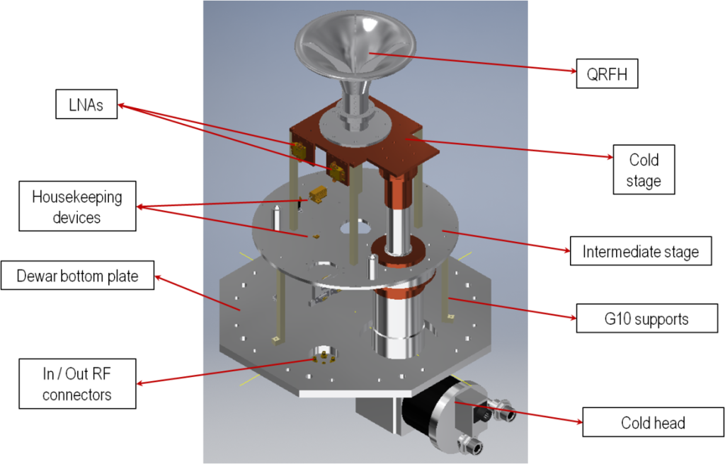
The VGOS broadband receiver covers the full 2-14 GHz frequency band. It is a cryogenic receiver cooled using a closed loop helium gas cooling system, which attains 8ºK in the cold stage. The front-end consists of a dewar with a dual linear polarization quadruple-ridged flared horn feed (QRFH), directional couplers for noisecal and phasecal injection and two ultra-low noise hybrid amplifiers developed at Yebes laboratories. The RF output signals from the dewar are sent to RF-over-fiber transmitters, allowing signal transportation through single-mode fiber back-ends room. In this place, the optical receivers are installed together with a RF distribution module and 4 up/down converters. These converters are fed by the outputs of the distribution module. They allow the selection of 4 dual polarization sub-bands in the range 2-14 GHz and its conversion to base-band to feed the VLBI back-ends that digitize the signal. 

Fig. 2: VGOS receiver dewar.
Fig. 3: VGOS broadband receiver.

GRAVIMETER

The gravimeter is an extremely sensitive piece of equipment and for that reason it is in a separate room of the building, resting on a concrete pillar about 8 m deep for contact with the bedrock. This room is always temperature and humidity controlled.

At the RAEGE Santa Maria Station, two types of gravimeters are currently installed:

  1. Superconducting Gravimeter (SG):

In October 2022, a iGrav-051 from GWR Instruments was successfully installed at the station. The iGrav is a superconducting gravimeter that employs a superconducting sphere as its test mass, subjected to a stable magnetic field produced by superconducting coils, cooled using a closed loop helium gas cooling system, in which the test mass is levitated. The iGrav can provide and accuracy of 1 nGal in frequency domain and 0.05 µGal in time domain.

Fig. 4: Superconducting Gravimeter.
  1. Graviton Relative Gravimeter:

“Spring” kind relative gravimeter that has a mechanical system electrically controlled, which simplifies most of the corrections and functions that must be applied in the records of the gravitational fields. It provides a final resolution of approximately 1 µGal and can achieve 0.1 µGal accuracy under ideal conditions. This resolution makes this type of gravimeter suitable for determining Earth tides, as well as other geophysical effects.

Fig. 5: Relative Gravimeter Graviton EG.

GNSS STATIONS

The RAEGE station of Santa Maria has two permanent GNSS stations, integrated into the IGS (International GNSS Service), EUREF, and REPRAA (Azores Regional Network of Permanent Stations). 

The stations is equipped with the following stations:

  • AZSM00PRT GNSS station: Leica GRX1200GG Pro receiver and a LEIAT504 LEIS antenna
  • RAEG00PRT GNSS station: part of the IGS network, Leica GR50 receiver and LEIAR20 antenna

GNSS receivers detect, decode, and process signals from GNSS satellites (GPS, GLONASS, GALILEO, etc.) which enable the location and displacement velocities of the antennas to be determined with varying degrees of accuracy.

The stations are equipped with multi-frequency geodetic receivers, capable of receiving multiple satellite constellations.

Fig. 6: RAEG GNSS Station.
Fig. 7: AZSM GNSS Station.

LOCAL-TIE

The six-pillar infrastructure that makes up the local-tie network at the RAEGE Station of Santa Maria allows referencing the positions of the VGOS 13.2 m radio telescope, and the positions of the antennas of the existing GNSS permanent stations: AZSM and RAEG.
Fig. 8: Local-tie network of the RAEGE Station of Santa Maria.

OTHER

SEISMOMETER

The RAEGE Station of Santa Maria has a three-component Trillium 120P/PA seismometer. This is a very broadband, low-noise seismometer suitable for both portable and fixed applications.

This seismometer has been in operation since 2019, forming part of the Network of Seismic Stations of the National Geographic Institute of Spain (IGN), and sharing real-time data with the Azores Seismovolcanic Information and Surveillance Center (CIVISA).

Fig. 9: Seismometer.

ACCELEROMETER

IGN has developed low-cost accelerometers known as SILEX, based on MEMS technology (Micro-ElectroMechanical System) to detect and record earthquakes with magnitudes that are perceptible to humans. A network of these equipment is implemented in areas of high seismic risk, such as the island of Santa Maria. This equipment measures the acceleration of the ground by recording strong movements that occur, for example, near tectonic faults.

Fig. 10: SILEX accelerometer.

HYDROGEN MASER

A space geodetic station requires at least one active hydrogen maser (atomic clock) which is used to generate a frequency reference for the station’s equipment. This type of atomic clocks guarantees high frequency stability, which is measurable and well-known. This is an essential feature in VLBI observations and allows preserving the coherence time at high signal frequencies. In VLBI observations, the reference signal generated by the maser, among other things, is injected into the signal captured from astronomical sources in order to generate a time stamp – the phase calibration tones (phasecal), which are later used as a basis for the correlation of VLBI data gathered by the different stations. VLBI observations would not be possible without a hydrogen maser.

At the RAEGE Station of Santa Maria is installed a iMaser from T4Science. The maser is in an isolated room of the building with controlled temperature and monitored pressure and humidity.

As VLBI is an unconnected interferometry technique (several stations are dispersed across multiple locations around the world), it requires the highest possible precision and stability in frequency patterns to maintain coherence between two remote stations over a long integration period.

Fig. 11: Hydrogen maser.

WEATHER STATION

The Vaisala WXT536 weather sensor installed at the RAEGE Station of Santa Maria belongs to a series of instruments that provide six of the most important meteorological parameters for a space geodesy station: atmospheric pressure, temperature, relative humidity, precipitation, wind speed and direction. These parameters are fundamental to complement VLBI observations and atmospheric models, since changes in these data affect signal reception by the radio telescope (introduce a temporal delay).

Fig. 12: Weather station.